15 Feb Fiber Optic Loss
Fiber optic loss (optical attenuation) is one of the most critical parameters affecting fiber optic network performance. During installation and certification, one question appears repeatedly: “What is the acceptable fiber optic loss value?” The answer depends on the cabling structure, application requirements, and the active equipment used in the network.
Understanding how attenuation occurs and how to calculate the optical power budget is essential for installers, integrators, and network designers. Incorrect loss calculations may lead to unstable communication, certification failures, or reduced transmission distance.
What is Fiber Optic Loss?
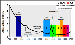
Fiber optic loss refers to the reduction of optical signal power as light travels through the fiber cable. Loss is typically measured in decibels (dB) and expressed as attenuation per kilometer (dB/km).
There are four primary sources of attenuation in fiber optic systems:
- Intrinsic fiber attenuation
- Connector insertion loss
- Splice loss
- Bending loss
For modern single-mode fiber cables, attenuation values are typically:
- 0.35–0.5 dB/km at 1310 nm
- 0.20–0.4 dB/km at 1550 nm
How to Calculate Fiber Optic Loss
Fiber optic loss calculation is based on the total optical link budget. A simple formula is:
Total Loss = Cable Loss + Connector Loss + Splice Loss
Example calculation:
- Cable length: 300 m
- Cable attenuation: 0.35 dB/km
- Connector count: 3
- Connector loss: 0.5 dB each
Cable loss = 0.3 × 0.35 = 0.105 dB
Connector loss = 3 × 0.5 = 1.5 dB
Total loss ≈ 1.6 dB
Three Methods to Determine Acceptable Fiber Optic Loss
1. Cabling-Based Optical Budget
TIA and ISO standards define maximum attenuation values for fiber optic components. Installers often use OLTS (Optical Loss Test Set) equipment to certify links according to these limits. This approach does not require knowledge of the future network application.
2. Application-Based Limits
When the application is known, acceptable attenuation can be determined directly from Ethernet standards. For example, Gigabit Ethernet over multimode fiber defines maximum channel attenuation limits depending on fiber type.
3. Active Equipment Power Budget
Transceiver specifications define transmitter output power and receiver sensitivity. The difference between these values determines the maximum allowable loss.
Example:
- TX power: −20 dBm
- RX sensitivity: −30 dBm
- Power budget: 10 dB
Why Fiber Optic Loss Matters in Real Installations
Even when installation distances are short, connector quality, splice accuracy, and cable handling can significantly affect attenuation values. Excessive fiber optic loss may cause intermittent communication problems that are difficult to diagnose.
Proper testing, correct connector cleaning, and accurate optical budget calculation ensure reliable network performance and long-term stability.
Fiber Optic Loss FAQ
- What is acceptable fiber optic loss?
Typically below 2–3 dB for short enterprise links, depending on application requirements. - What causes fiber optic attenuation?
Absorption, scattering, connector insertion loss, splices, and bending. - What is optical power budget?
The maximum loss allowed between transmitter and receiver while maintaining stable communication.