
What Is MPO Cable? Connectors, Fiber Counts and Compatibility
What is MPO cable? It is a fiber cable assembly terminated with a multifiber push-on connector, allowing several fibers to be connected through one interface. Its usefulness comes from the connection density and installation format. The connector does not, by itself, define a data rate or guarantee compatibility with a transceiver.
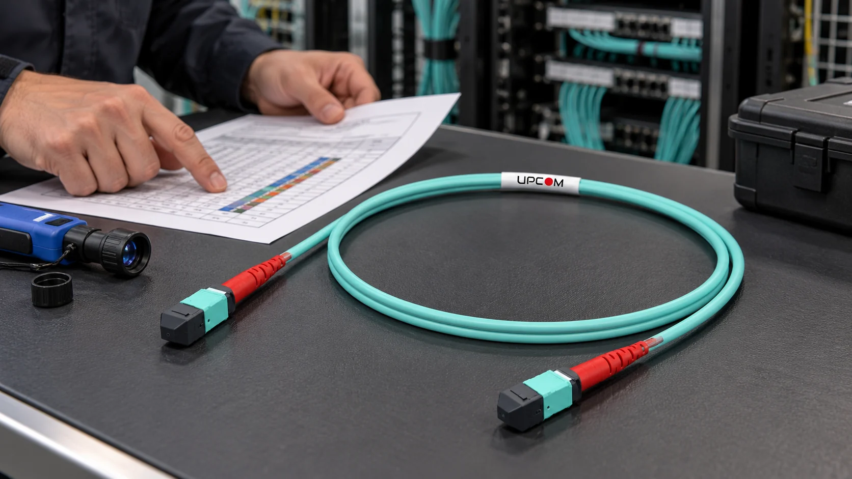
MPO and MTP: use the correct terminology
MPO means multifiber push-on. MTP is a registered trademark of US Conec for its MPO-style connector products. A specification should identify the required connector manufacturer or performance grade when that distinction matters, rather than treating the two names as a complete technical description.
The connector holds several fibers in a common ferrule. Alignment pins and the mating interface position the ferrules; the key and fiber mapping determine orientation and channel continuity. The assembly may be a trunk between two multifiber interfaces or a fanout that separates the fibers into individual connector legs.
The UPCOM MPO cable assembly range includes trunks and LC fanouts. Choose the configuration after identifying the equipment at both ends.
Connector positions and active fiber count are different
A connector described as MPO-12 has twelve fiber positions. An application can use fewer active fibers than that connector provides. For example, a parallel optical link may use four transmit and four receive fibers in a twelve-position interface, leaving four positions unused.
Other applications use different row arrangements, lane counts or duplex connections. “100G” is therefore not a sufficient ordering description. Neither is a request for a twelve-fiber cable without the optical interface and mapping.
| Optical module example | Connector interface | Cabling implication |
|---|---|---|
| 100GBASE-SR4 | MPO-12; eight active fibers | Match the multimode fiber grade, mapping and module reach specification. |
| 100GBASE-PSM4 | MPO-12; eight active fibers | Uses parallel single-mode paths; an SR4 multimode assembly is not an equivalent substitute. |
| 100GBASE-LR4 | Duplex LC | Uses wavelength multiplexing over a fiber pair; it does not require a 24-fiber MPO connection. |
LC is a connector format, not a 1G or 10G speed limit. The optical module, fiber and link conditions establish the supported application.
Trunk, fanout or cassette: select the connection path
A trunk connects multifiber interfaces directly or forms the backbone between distribution components. A fanout converts one multifiber interface into separate legs, often LC. A cassette can provide the same kind of presentation within a panel, while adding connections and a defined internal fiber map.
A physical fanout does not make every breakout application work. The transceiver and host equipment must support the intended channel arrangement. Confirm the module part numbers and breakout mode before ordering a cable based on the number of LC legs.
Where termination space is the limiting factor, compare fiber patch panels together with the connectivity components. Include rear cable access, strain relief, cassette depth and service-loop storage in the layout.
Polarity, pinning and polish must agree end to end
- Polarity: verify the complete transmit-to-receive path through trunks, adapters, cassettes and patch cords. A Type A, B or C label on one component does not describe the whole channel.
- Pinning: identify the pinned and unpinned mating interfaces. State the required connector gender at each end in the assembly drawing.
- Polish: match the specified UPC or APC interface. Do not mate unlike endface geometries.
- Orientation: record key orientation, fiber numbering and row arrangement. Do not extend a twelve-position mapping drawing to another format without checking it.
Use the MPO polarity, gender and loss-budget checklist for the detailed channel checks. The approved wiring drawing is the final reference for a project.
Build the optical loss budget before buying the assemblies
Every mated connection consumes part of the link budget. Include the transceiver-to-transceiver path that the application specification requires: trunks, fanouts, cassettes, patch cords and splices. Use the maximum specified component losses for design rather than a favorable factory measurement from one sample.
For an illustrative short channel with four mated connections specified at 0.35 dB each, those connections alone account for 1.40 dB. Fiber attenuation and any other passive losses still have to be added. This arithmetic is not an application limit; compare the resulting total with the actual module specification and required margin.
A higher-density connector also puts more endfaces in one mating operation. Inspect, clean with the appropriate multifiber tool and reinspect before connection. Protect unused interfaces with clean caps, and retain the assembly test results with the installation records. Our fiber optic loss guide explains how component losses accumulate.
What to include in an MPO cable enquiry
| Specify | Useful detail |
|---|---|
| Application | Equipment and optical module part numbers, data rate and any breakout mode. |
| Fiber | Single-mode or multimode grade, total fibers and active fibers. |
| Ends | Connector format, pinning, polish, key orientation and fanout layout. |
| Mapping | Approved polarity drawing and fiber numbering. |
| Mechanical construction | Overall length, fanout lengths, jacket, diameter, pulling arrangement and installation environment. |
| Acceptance | Maximum insertion loss, applicable return-loss requirement and required test documentation. |
This information makes quotations comparable. A cheaper assembly with the wrong map, fiber grade or optical loss specification is not an equivalent offer.
Frequently asked questions
Does every 100G link use MPO?
No. Some 100G interfaces use MPO, while others use duplex LC. Confirm the exact optical module rather than ordering by data rate alone.
Can I replace an MPO trunk with an MTP-branded assembly?
Only after confirming the complete specification: mating format, pinning, polish, mapping, fiber type and optical performance. The brand name does not replace those checks.
Is a twelve-position connector always a twelve-active-fiber link?
No. Some parallel applications use eight active fibers in a twelve-position interface. Distinguish ferrule positions, installed fibers and active lanes in the enquiry.
Order the assembly against an agreed interface drawing
Send the module references, connector configuration, polarity drawing and required lengths. UPCOM can review the assembly configuration before quotation.