
Fiber Optic Cable Blowing: A Practical Installation Guide
Fiber optic cable blowing installs suitable fiber cables into ducts using controlled mechanical feed and compressed air. Often called fiber jetting, it can reduce concentrated installation loads compared with pulling, provided the cable, duct, machine and air supply form a compatible system.
This guide covers route preparation, cable-to-duct sizing, compressor selection, machine setup, safe operation and fault diagnosis. Use the operating manual for your machine and the cable and duct manufacturers' installation limits when setting force, speed and pressure.
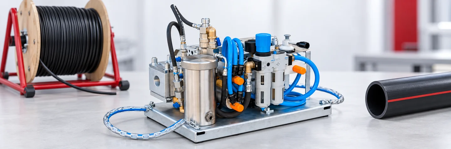
How Fiber Optic Cable Blowing Works
The machine feeds cable into the duct while moving air transfers drag along its surface. The mechanical drive helps overcome initial resistance, while the air assists onward movement. Cable stiffness, available air space, sheath friction, bends and reel resistance all affect the result.
This guide describes air-assisted installation without an end piston. Some suppliers use “blowing” and “jetting” differently; methods that add a piston or parachute need their own approved procedure. Do not interchange the force assumptions of these methods.
Suitable applications include access networks, backbone routes, campus links and FTTH deployment. See how a cable blowing machine works for the operating principle.
Fiber Optic Cable Blowing Equipment and Tools
- A blowing machine with cable-specific rollers or belts, guides, seals and duct holders.
- A compressor with verified air delivery at the required pressure, compatible hoses and rated couplings.
- An aftercooler and moisture separation where required by operating conditions.
- A stable reel stand or drum roller with controlled payoff and suitable load capacity.
- Duct cleaning sponges, approved passage-test tools and pressure-integrity test equipment.
- Compatible blowing lubricant when required, a suitable cable-end cap or guide, and a safe receiving arrangement.
- Communication between entry and exit teams, personal protective equipment and the relevant manuals.
An electric or drill-powered feed system still needs compressed air for the blowing operation. Motor power and duct air supply are separate requirements.
Machine Components and Setup Limits
Drive and cable guides
Use the approved roller or belt profile and align the cable straight through the machine. Set grip pressure and feed-force protection for the cable construction; excess clamping can damage the jacket.
Seals and duct holders
Use seals that fit the actual cable OD and holders that fit the duct connection dimensions. A tight seal must not create excessive drag. Confirm the duct cannot move out of its clamp under pressure.
Air controls
Check the regulator, gauges, air path and coupling ratings. A compressor outlet reading does not prove that the required air reaches the machine after hose losses and leakage.
Force and speed protection
Check the machine's clutch, torque limit or automatic stop where fitted. Follow the manufacturer's calibration procedure before production installation.
Fiber Optic Cable Blowing Preparation
Inspect and prove the duct
Record section length, duct OD/ID, bends, elevation changes and intermediate access points. Inspect couplers and transitions. Clean and remove water using the duct supplier's method, then prove passage with a correctly sized approved mandrel or ball. A cleaning sponge can pass a partial obstruction and does not replace a passage test.
Check pressure integrity according to the duct system's procedure and ratings. Use a capture device at the receiving end for expelled test tools, and keep people clear of the discharge path.
Prepare the cable and reel
Inspect the drum and jacket, measure actual cable OD, and confirm the cable is approved for blowing. Obtain its installation bend limit, temperature range and permitted mechanical loads. Use a suitable sealed end cap or guide without exceeding the available clearance.
Set the reel for smooth, controlled payoff following the cable supplier's handling instructions. Avoid crossed wraps, dirt at the machine entry and sharp bends between the drum and drive.
Plan lubrication
Confirm the lubricant is compatible with the cable sheath and duct lining. Some self-lubricating microducts may not need added lubricant. Follow the applicable supplier instructions for product, quantity and application method; pooled lubricant can obstruct the route.
Duct lubricant and pneumatic motor oil serve different purposes. Use the specified motor oil only in the drive lubrication circuit; do not treat it as a cable blowing lubricant.
Review UPCOM cable blowing lubricant and fiber optic cabling installation practices alongside the relevant manuals.
Cable-to-Duct Ratio: Diameter vs. Area Fill
Use the duct internal diameter (ID) for the installation calculation. Duct outside diameter may determine the machine connection tooling, but it does not describe the available air space. The two calculations below must not share an unlabeled percentage.
Corning AEN096 recommends a diameter-based target of 50–80% for the microcable applications it covers. Treat this as application-specific guidance, not a universal acceptance range for every cable. Check the selected cable and duct combination with their manufacturers.
A close fit restricts air space; a very loose fit changes air demand and cable behavior. Cable stiffness and route bends also matter. See the Cable Blowing Distance & Performance Guide for planning context.
Compressor Pressure and Airflow for Fiber Optic Cable Blowing
Select air delivery at the intended operating pressure, rather than comparing only maximum bar ratings. Larger duct ID generally requires more air volume. Pneumatic feed motors also consume air; check whether the quoted machine requirement covers the complete operation or the drive alone.
The following figures are broad conduit-installation references from Dura-Line, not prescribed settings for every UPCOM model. Final sizing must account for cable/duct combination, route, pneumatic drive consumption and losses through hoses and fittings.
| Duct ID | Indicative air volume | Use |
|---|---|---|
| Microduct: 5.5–14 mm | Approximately 0.28–1.7 m³/min | Initial microduct sizing reference |
| Microduct: 16–20 mm | Approximately 2.8–10.6 m³/min | Larger microduct air demand |
| Standard conduit: 1–2 in. (25.4–50.8 mm) | Approximately 4–12 m³/min | Larger telecom duct reference |
Read the air compressor selection guide for project sizing. Compressor model names are intentionally omitted from this sizing table: the same model can have different pressure variants and delivered air volumes.
Fiber Optic Cable Blowing Safety Checklist
- Use trained operators, eye and hearing protection, and site-required PPE.
- Agree entry/exit communication and stop signals; verify the emergency stop before starting.
- Keep hands, clothing and tools clear of rollers, belts and reel pinch points.
- Secure rated hoses and couplings using the restraint arrangements specified for the equipment.
- Keep the duct outlet controlled and clear of people; secure the receiving capture arrangement for cleaning and test operations.
- Stop the drive, isolate the supply and verify zero residual pressure before opening the chamber or changing seals and connections.
- Never raise force or pressure beyond an approved limit to recover a stalled cable.
Step-by-Step Fiber Optic Cable Blowing Procedure
Complete duct proofing and cable checks first. The sequence below is a field framework; the selected machine's operating procedure determines the detailed order and settings.
Set up the machine and reel
Place the machine on a stable support and align the entry with the duct. Arrange controlled reel payoff and maintain the cable's specified installation bend limit.
Fit the cable and duct tooling
Install the approved guides, seals, rollers or belts and duct holder for the measured dimensions. Check cable grip, freedom of movement and the security of the duct connection.
Calibrate feed-force protection
Follow the manufacturer's procedure for torque, clutch or stop-force adjustment. Where the manufacturer specifies a crash test, perform it using the approved test arrangement before the run; do not improvise a blocked-duct test on the installed route.
Prepare lubrication and connect air
Apply compatible lubricant if required. Connect the rated air system with valves in the positions specified by the manual, then check sealing and regulated pressure. Confirm the receiving team is ready.
Start with controlled feed
Introduce feed and air in the machine manufacturer's specified sequence. Begin at a conservative feed speed and increase gradually only while movement is stable. There is no universal 40–60 m/min starting speed or fixed initial pressure for all cables.
Monitor and stop on abnormal behavior
Watch cable travel, installed length, reel payoff, pressure and jacket condition. Stop feed on a stall, buckling, slipping, abnormal heating or a sudden pressure change. Isolate and depressurize before hands-on inspection. Correct the cause and repeat the required setup checks before a controlled restart.
Finish, seal and verify
Coordinate arrival with the receiving operator, stop safely and release pressure. Leave the required slack without violating bend limits, protect cable ends and seal duct entries. Complete the optical tests required by the project and record the installation results.

Which UPCOM Machine Fits the Cable Blowing Job?
Choose by actual cable OD, duct connection size, drive preference and route conditions. A model's widest cable range does not make it suitable for every smaller cable.
| Model / drive | Cable OD | Duct / tooling range | Selection context |
|---|---|---|---|
| MikroFOK Pneumatic | 1–6 mm | 6–20 mm duct OD | Small cable and microduct work |
| DrillFOK Drill-powered feed | 1–8 mm | Confirm selected connection tooling | Portable small-cable installation; compressed air still required |
| ElektroFOK Electric | 1–8 mm | 4–18 mm published duct range; confirm OD/ID for the selected tooling | Small-cable work with adjustable electric feed |
| MiniFOK Pneumatic | 2.5–12 mm | 7–40 mm duct tooling, by configuration | Mixed access and distribution cable projects |
| MiniFOK Genius | 4–8 mm published reference | 14–16 mm published tooling reference | Confirm the supplied configuration with UPCOM; validated speed and distance figures are not published |
| FOK Pneumatic | 9–22 mm | 20–50 mm duct OD | Larger telecom feeder and backbone cables |
| HidroFOK Hydraulic | 9–24 mm | 20–60 mm duct OD | Larger cables and demanding routes |
FOK and HidroFOK publish up to 3,000 m under the stated reference combination of 12 mm cable and 40 mm duct. This is a conditional capability, not a promised distance for every route. Maximum speed, typical speed and daily installed output are different measures.
Use the distance and performance comparison for the complete published figures and planning assumptions. Send cable OD, duct OD/ID, route length, bend information and available compressor specifications when requesting a configuration.
Troubleshooting Fiber Optic Cable Blowing Problems
Stop abnormal operation first. Isolate and depressurize before inspecting any pressurized connection.
| Symptom | Checks | Corrective action |
|---|---|---|
| Cable stops or buckles | Obstruction, tight bend, excessive push force, unsupported entry | Check route proofing and force protection; correct the cause before restarting |
| Drive slips or marks the jacket | Wrong tooling, dirty contact surfaces, excessive or insufficient grip | Fit the approved tooling and reset grip according to the manual |
| Pressure drops during feed | Seal leakage, hose restrictions, coupling leaks, inadequate delivered air | Inspect the air path and verify volume at working pressure |
| Performance falls after a good start | Reel drag, route bends, water, air temperature, lubricant distribution | Inspect supply and route conditions; consider a shorter planned section |
| Jacket heats or scuffs | Misalignment, friction at seals, slipping drive, incompatible lubrication | Stop and inspect; correct alignment and tooling, then reassess cable condition |
For model-specific setup and recovery information, use UPCOM Field Support.
Long Routes and Staged Installation
Plan intermediate access
Use accessible sections when route geometry or cable handling makes a single run unsuitable. Where a continuous cable must be installed in stages, use an approved figure-eight storage arrangement or cable fleeter and preserve bend limits.
Use engineered tandem arrangements only
Multiple machines or intermediate air assistance require a coordinated, manufacturer-approved plan for pressures, feed forces, communications and stops. They are not a generic “dual-pressure” adjustment to apply to any route.
Do not add pulling assistance or a piston to the method described here without an approved installation procedure for that cable and duct system.
Temperature, Moisture and Route Geometry
Temperature and compressed-air treatment
Keep the cable, lubricant and equipment inside their rated operating ranges. Compression heats air; use suitable cooling and moisture separation when necessary. Check air conditions at the machine rather than relying on ambient temperature alone.
Water and contamination
Remove water and debris before installation. Keep cable entry clean and seal unused duct ends to reduce contamination between work stages.
Bends and elevation
Repeated bends, tight radii, coupler transitions and elevation changes can reduce achievable distance. Weather affects handling and air treatment; it does not directly determine a cable's trajectory inside a fixed duct.
Best Practices and Installation Records
Record cable and duct identifiers, measured dimensions, section length, proofing results, machine tooling, compressor delivery, pressure and force settings, lubricant used, installed length, stops and optical acceptance results.
Use these records to plan repeat sections and investigate faults. Do not estimate daily output by multiplying maximum machine speed by a full shift; setup, section changes and handling take time.
Related Guides and Technical References
- Cable blowing machine range
- Cable blowing distance and performance
- Air compressor selection
- Fiber optic cabling installation practices
- Cable blowing lubricant
- Model-specific field support
- Corning AEN096 — Micro Cable Air-Assisted Installation Considerations: microcable sizing, preparation and installation protection.
- Dura-Line — Choosing the Right Air Compressor: pressure, duct-ID air volume and after-treatment.
- FOA — Air Blown Fiber: installation overview.
External guidance supports the installation principles. The machine manual and the selected cable and duct documentation determine project-specific limits.
Fiber Optic Cable Blowing FAQ
What is fiber optic cable blowing?
Fiber optic cable blowing uses controlled mechanical feed and compressed air to install a suitable cable into a prepared duct. Moving air assists the cable along the route.
What cable-to-duct ratio should I use?
State whether the percentage is a diameter ratio or area fill, and use duct internal diameter. A 6 mm cable in a 10 mm duct ID has a 60% diameter ratio and 36% area fill. Follow the selected cable and duct manufacturers' guidance.
What compressor do I need for fiber optic cable blowing?
Check delivered air volume at working pressure for the actual duct ID, cable and route. Include pneumatic drive consumption and hose losses. Maximum compressor pressure alone does not establish suitability.
Does an electric blowing machine still need compressed air?
Yes, for the air-assisted blowing operation described here. Electric or drill power drives the cable feed; the compressor supplies the duct air.
Should I restart a stalled cable at maximum pressure?
No. Stop the drive, isolate and depressurize before inspection, then identify and correct the cause. Restart under the machine manufacturer's procedure within the approved cable and equipment limits.
Does a cleaning sponge prove the duct is unobstructed?
No. A sponge can pass a partial obstruction. Use the duct manufacturer's approved passage test as well as cleaning and pressure-integrity checks.
Can every route achieve the published maximum blowing distance?
No. Published maximums depend on a specific cable, duct and installation setup. Bends, air delivery, temperature, lubrication and reel handling can reduce field performance.
Is lubricant always required?
Not for every duct system. Check the duct lining and cable manufacturer's guidance, especially for self-lubricating microducts. Where lubricant is needed, use the specified compatible product and quantity.
Match the machine to your cable and route
Share cable OD, duct OD/ID, section length, bends and compressor capacity. UPCOM can check the machine and tooling configuration for your project.