10 Jan Cable Blowing by Pressurized Air / Fiber Optic Cable Blowing Procedure
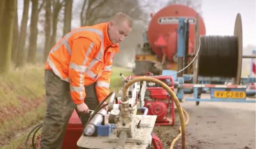
Cable Blowing (Sometime called air assisted cable blowing, Cable Blowing by Pressurized Air, air blowing, jetting and all these words are describing method of cable blowing with pressurized air) Cable Installation has been always a challenge for installers. There are several method to lay the cable into duct/conduits and air assisted cable blowing is one of the newest and easiest method to install the cable into pre-installed ducts with the help of a cable blowing machine.
What is Cable Blowing by Pressurized Air
The push pull (piston) blowing process of cable construction is very common to field workers. Thread a cord through the pipeline, connect the line and pull or tug the cable into the pipeline. The force used to pull the cable normally comes by a pulling of the seam by the capstan or by hand. This strength is required to overcome the frictional resistance of the cable to motion. The maximum strength permissible on the cable is limited to the installation length.
The high air speed blowing has to overcome the same frictional force to move the cable, but it does so using a very different method. The power in the air blow comes, first, from the mechanical mechanism that drives the cable; and, second, from the air force passing on the jacket of the cable or, respectively, from the air force at the front end of the cable on the piston, missile or carrier.
These two types of air assisted cable blowing are shown below:
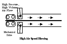

Either way, the pushing device, though common, the aim of the air flow from the duct are different. In the high air speed blowing method, the duct is completely open and a high volume of air is blown through it. This “compressed air” pushes the cable and pushes it forward at the speed that the pusher will support. The cable has no pulling force at the front end, only a mechanical thrust at the rear and an air drag force distributed along its length.
The piston (push / pull) method connects a missile or carrier in front of the cable. The missile is pushed by the force of air pressure through the duct and the missile pulls the cable, hence the term push/pull assembly. Because the duct is blocked or at least partially blocked by the piston, this method does not require as much air flow as the high air speed blowing method, and flows of 340 to 510 NaN are typical during push / pull piston installation.
Cable Blowing by Pressurized Air Vs Fiber Optic Pulling
While any type of cable can be blown into the duct, blowing is particularly useful for installing outdoor type fiber optic cables. Fiber optic cable is light and flexible. Long, continuously cable lengths are always desired for an easier blowing. Both factors are important to determine the power of the cable blower we will be using.
When pulling, when a cable runs through a pipe bend, the pulling force on the cable actually pushes the cable towards the bend. An exponential friction force is created, which is much greater than that occurs only with the weight of the cable. Thus, the accumulation of bending angles greatly reduces the possible length of pull. However, there is not much bending in fiber optic cable pulling between countries, or is it?

The flexible continuous duct brings “hidden folds”. These are inherent undulations or waves from the reel memory as drawn here.
While these waves can be minimized, they cannot be completely eliminated. Typical displacements of a few centimeters to one meter increase tensile stress by 3 to 200 times.
In fiber optic pulling, maximizing distance means minimizing duct fluctuations. A thick-walled inner duct with a diameter of 5cm or more can be positioned “straighter” than a 2,5cm or 3.18 cm duct, but this cost is premium. Multi-chamber ducts keep the inner duct with a flat and rigid outer surface, again at a cost and labor addition. The Plowed duct is straighter than trenched duct. The fact is that, pulling cable into open trenched inner duct isn’t a brilliant idea in practice. The amount of undulation simply makes pull lengths too short.
Duct bends, including corrugations, do not limit blowing processes, especially high air speed blowing, as much as in conventional cable pulling processes. In high air speed blowing, the cable is not pulled into the bend with a large pulling force. However instead is pushed through the bend by a lower, local air pushing force.
In the push / pull blow, the pull from the piston is partially offset by the pushing force from the mechanical pusher. This somehow balances the effects of the bends. A more detailed analysis of the bending performance differences in high air speed blowing against the push / pull can be found on another of our article coming soon.
Key Factors in Cable Blowing by Pressurized Air
In air-assisted cable blowing installations, there are several important factors that need to be controlled to achieve the best performance. The first is the flexibility of the cable. A very flexible cable cannot be pushed in smoothly without being gathered. While more rigid cables are easier to push, they consume more force bending and twisting in duct bends.
It is important to choose the right cable for optimum blowing. While most fiber cables can be blown, some cables are designed specifically for blowing. Check with your cable manufacturer for recommendations.
Duct type is another important factor in optimized cable blowing. Circumferential ribbed or wavy ducts that disrupt the air flow are not satisfactory. Smooth wall and longitudinal ribbed HDPE pipes are preferred.
Duct type is important but air pressure that duct can hold is very important too. The duct should hold up to 9 bar of air pressure without leakage. Duct connections are critical. Inserts should not reduce the inner diameter of the duct. Internal duct couplers specially designed for blowing are commercially available and recommended.
Friction Reduction
A final factor in optimized blowing is the reduction of friction. Theoretically, the maximum length that can be blown in any case is proportional to the friction coefficient. If the friction coefficient can be reduced three times, the practical installation length will triple.
Lubricating oil is critical in optimized blast. Quality factory lubrication is useful inside the duct. But the most consistent results come from the field application of specially designed inflating lubricants. Cable pull lubricants do not work well for blowing and special blowing lubricants are recommended. Generally, inflator lubricants are used in relatively small quantities (300 ml at 300 meters).
Researches about friction reduction
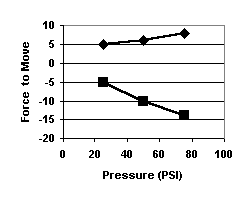
Some research results on lubrication in the blowing process are presented in the graphic below. In these studies, the forces on the cable at various air pressures and volumes were measured by deactivating the mechanical pushing unit in a high-speed cable blowing machine. Moving air was pushing a MDPE-sheathed fiber cable that was fully passed through a multi-loop HDPE flat-wall inner duct.
The graph shows a greased coefficient of friction in the range 0.08 versus 0.60 for un-lubricated cable. For flat installations, this lubrication level can result in an increase in installation length of more than 5 times.
Air pressure (bar) is plotted on the x-axis and the force (kilograms) required to move the cable on the y-axis. A negative force indicates that the cable is trying to advance into the duct and should be held back.
Field Comparison and Economics
Blowing processes usually lay the cable at a higher speed than pulling it into the duct. Economics can be particularly advantageous for large jobs where equipment cost can be amortized. Field teams report that 15000 m of cable is laid per day. Common cost factors are presented below:
| PULLING | BLOWING | |
| Equipment | 1 – 12 M $ | 15 – 45 M $ |
| Speed | 1 m | 1.8m |
| Length | 460 – 1100 m | 920 – 2500 m |
| Pull Line | Required | Not Required |
Long, continuous length blowing cables can be installed with the stepped blowing units. Using units in series to do this cascading or continuous runs can minimize the need to form eight.
Blowing requires good planning and preparation, especially duct preparation. All units require seals sized to the cable to prevent leakage from the pressure chamber around the input cable. Before starting work, suitable size cable seals and nutrings should be obtained from the supplier.
General Field Procedures
- Make sure you have a duct device with pressure-resistant joints that is properly mounted. Test this by closing one end of the duct and using a sealed blower to apply pressure to the duct. Any large volume of air pressure can not be lost by the duct. About pressure ducts, be cautious. Sand and shells can be blown from the duct and duct joints of bad consistency can fly out.
- Cover the front end of the cable and blow at high air velocity so that it will not be trapped in the duct. To fit the outer diameter of the cable you are mounting, make sure that you have air seals.
- Clean and dry the ductl, and prove it. If not done before, to guarantee that the groove is not crushed, blast onto a rough mandrel. Next, at high pressure, blow a tight-fitting foam carrier into the duct. At around 30m / sec, the foam can advance through a clean pre-installed duct. Repeat the procedure if extra water or dirt falls out of the duct. Dry the duct with a stream of dry air if necessary.
- Inject the recommended volume of lubricant and blow it out from another foam carrier for high air velocity devices (no missiles). Most of the lubricant is pumped in front of the projectile in the reciprocating machines and some is placed behind it.
- Plug the blowing machine to the duct. Plug the piston into the cable and insert the piston into the duct for the push / pull devices. For high air speed blowing, push the cable up to 30 m by hand into the duct. In the blower, lock and seal the cable and air chamber. For all procedures, obey the machine manufacturer’s instructions.
- Check all ties that are pneumatic and hydraulic. Open up the air gently and watch it go!
Summary

Cable Blowing by Pressurized Air installation of fiber optic cable has proven to be both practical and economical. The technology is gaining popularity not only in the USA and in Europe, but all over the world. The process is quite different from shooting and requires focusing on factors other than shooting. By joining these factors, a plumber can quickly learn and use air support methods.
11 reasons why the future belongs to fiber optic
11 Reasons Why the Future Belongs to Fiber Optic “The future belongs to fiber optics!” This bold claim is backed by compelling reasons. Fiber optic technology is not just an upgrade—it’s a transformative infrastructure shaping how we connect, communicate, and consume information. Here are 11......
19″ Rack Cabinet
What is a 19” Free Standing Rack Cabinet? 19” free standing rack cabinets provide a robust, cost-effective enclosure solution. PDU mounting or connectivity on both the front and rear of the cabinet. The Free Standing 19” Rack cabinets are ideal for high-density data center environments,......
5 Fan Facts About the Fiber Optic Cables
Fiber optic cables are a type of cable that use glass or plastic fibers to transmit data. Here are some interesting facts about fiber optic cables: Speed: Fiber optic cables are capable of transmitting data at much faster speeds than traditional copper cables. This makes......
Advancements in Fiber Optic Technology: Improving Bandwidth and Transmission Rates
Fiber optic technology has revolutionized the way we communicate, providing faster and more reliable data transmission over long distances. The use of fiber optic cables has become increasingly popular in recent years, and the technology continues to evolve at a rapid pace. In this article,......
All about fiber optics
What does a fiber optic cable do? A fiber optic cable is a type of cable that uses glass or plastic threads to transmit data. These threads, or fibers, are extremely thin and are surrounded by a protective coating. They are able to transmit data......
Best Fiber Optic Cabling Installation Practices Guide
Fiber optic cabling installation is a complex process that requires specialized knowledge and equipment. Here are some best practices for fiber optic cabling installation to ensure a successful and reliable installation: Plan the Installation: Before starting the installation, it is important to plan......
Cable Blowing by Pressurized Air / Fiber Optic Cable Blowing Procedure
Cable Blowing (Sometime called air assisted cable blowing, Cable Blowing by Pressurized Air, air blowing, jetting and all these words are describing method of cable blowing with pressurized air) Cable Installation has been always a challenge for installers. There are several method to lay the......
Cable Blowing Lubricant
Cable blowing lubricants are specially formulated lubricants used to lubricate cables as they are being pulled through conduits or other tight spaces during the installation process. The lubricant is applied to the cables before they are pulled, and it helps to reduce friction and make......
Cable Blowing Machine work
Cable blowing machines, also known as a jetting machine or fiber optic cable blowing machine, is a device used to blow cables, such as fiber optic cables, into ducts or conduits. The machine works by using high-pressure air or water to propel the cable through the......
Cable Spooling Machines: The Ultimate Guide to Efficient Cable Handling
In industries such as telecommunications, energy, manufacturing, and infrastructure, the need for Cable Spooling Machines have never been greater. Traditional manual spooling methods can lead to inconsistencies, labor-intensive processes, and increased cable damage. This is where cable spooling machines revolutionize operations by ensuring precise, automated, and......


